Dipole Antenna
26 May 2020
A dipole antenna is probably the easiest to build. This will be a 1/2 wavelength dipole, designed for the 20m HAM band (14.1 MHz).
Antennas must be tuned to the frequency that they will be used for. Some antennas like dual-band WiFi antennas are cleverly designed to be resonant at multiple frequencies (being 2.4 GHz and 5 GHz). For my first antenna, I decided to go for a simple single-band antenna to keep the math simple and the number of things that I could mess up to a minimum. For a dipole, the total length of the antenna dictates the wavelength it is tuned for, and thus the frequency it is tuned for.
When an antenna is tuned to a frequency, that means its Standing Wave Ratio (SWR) is lowest at that frequency. Higher SWR means more power will be reflected back to the radio, resulting in less of it being turned into radio waves and potential damage to the radio. This mostly matters when transmitting (TXing).
The main part of a dipole is the center: where the feedline (most likely 50-ohm coax cable) meets the actual antenna. The antenna is connected like so:
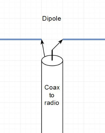
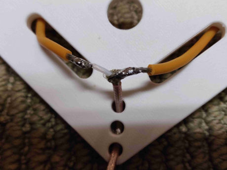
Cutting open some coax reveals a shielding made of small wires woven together and a center wire. The jacket is soldered to one side of the antenna and the center wire to the other. A dipole really is just 2 pieces of wire soldered to the feedline. Of course to make it more convenient, I used a very short piece of coax to solder to the antenna so I can disconnect the long length of coax running to my radio.
Antennas need to be tuned to the desired frequency. With any type of dipole, tuning is done my changing the physical length of the wires. Next, I will go through the math to determine how long the wires should be.
We need to convert 14.1 MHz into a length in meters so we can start building. The formula relating frequency to wavelength is:
ƒ = 300/λ
ƒ = frequency in MHz
λ = wavelength in meters
300 comes from the speed of light, which is actually 299,792,458 m/s
Rearranging this for λ and plugging in f=14.1MHz gives us λ=21.28m. For a 1/2 wavelength dipole, the total length is λ/2, or 10.64m
From the image above, we can see that the dipole actually consists of 2 pieces of wire. Each of these will be 1/2 the total length, or 5.32m. Leave a little extra for securing the wire to stuff. This will not fit easily inside my house.
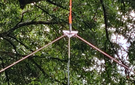
Something must be used to hold these wires/cables together. Solder is not meant for mechanical loads. I 3D printed a center piece, but a piece of wood with some holes drilled through would have worked just as effectively. Just make sure it's not metal.
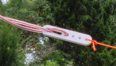
The ends must also be secured to insulators. The insulators serve as an end to the wire that keep the antenna from touching any metal while also making it more convenient to install. I 3D printed some more parts. Again, anything non-conductive will work fine. The other side of the insulator has some rope and carabiners to make the antenna easy to install anywhere.
There are a few things to consider when installing a dipole: height, orientation, and angle between the two wires. More height = more better (until you get into take-off angles, SWR optimization, etc.). My antenna is slightly under 0.5 λ off the ground, measured from the center. I have yet to encounter issues.
Orientation matters since most of the power from the antenna is radiated perpendicular to the wires. Contacting a station to the North is much more reliable when the wires are running East-West.
The final consideration is the angle between the 2 wires. The radiation pattern is affected by this as well as the SWR. My available space dictates this more than anything, so my angle is about 120°. Anything larger than 45° should be fine. Anything smaller will start to dramatically affect the SWR
Using a SWR meter, antenna analyzer, or anything that includes a SWR meter, the SWR of the antenna can be measured over a range of frequencies to determine both the center frequency and the efficiency at that frequency. Unfortunately, theory != practice, so my center frequency was pretty far off, even with careful measurement. Making the antenna longer will lower the center frequency, shorter will raise it. Using the formula
the correct length can be calculated rather than guessed. One side of the equation is the current frequency and length, the other is the desired frequency and the target length. Solve for target length.
After a few rounds of adjusting the length, I managed to get a SWR of 1:1.23 (or just 1.23). For context, 1:1 is 100% efficiency and 1:2 is 90% efficiency. It's not a linear scale though, so we can't just do some division to find my exact power efficiency.
When doing research for this, I found many articles recommending a balun. A balun is a circuit/device that goes between the coax and the antenna. It apparently helps with unwanted RF radiation from the coax since the coax shielding is physically and electrically different from the center wire, creating an unbalanced system which feed into the dipole (a balanced system). My antenna seems to work fine without it.
