Teensy Based Guitar Pedal Prototype
10 December 2019
See this page for a more complete/pedal board-ready Teensy based pedal that I built.
After making my distortion pedal, I wanted to make more pedals. I eventually discovered the Teensy Audio Library and Audio Board, which became the base for a programmable, digital guitar pedal. This is a massive project for me involving case design, user interface design, PCB design, Digital Signal Processing (DSP), and probably a few topics that I'm forgetting. If you are unfamiliar with how pedals work, I suggest you read the post on my distortion pedal first.
Check my github for all my project files.
The pedal has 2 effect banks with independent controls for each. Each bank can only have 1 effect active (or not active) at a time.
Effect 1 is applied to the signal first and can be converting the signal to a square wave, performing bitwise operations on the signal with a derived signal, and maybe some other dramatic effects.
Effect 2 comes next and consists of more subtle effects like reverb or an LFO connected to a band-pass filter.
At the very end of the signal path is a low-pass and high-pass filter. The controls for these are linked to Effect 1 since they affect Effect 1 the most. These are always active. However, their min/max settings allow them to be adjusted so they do practically nothing to the signal. (nothing I can hear at least)
The case was modeled in Fusion 360 and 3D printed. Its mostly just a box with a few features: holes to stick buttons and knobs through, a nice "chamfer" along the edge, and slightly thicker corners with holes for M3 screws to secure the base plate. The base plate is just a rectangle with holes for screws.
If my woodworking skills were up to the task, I would have gone with a wood case, but 3D printing was easier for me. Surprisingly, my foot doesn't crush the case when I hit the stomp switches.
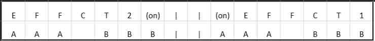
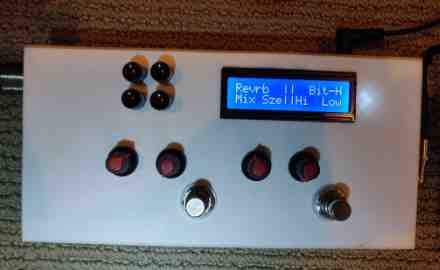
The user interface is a 16x2 LCD display which has some advantages and drawbacks. It is easy to program for and easy to implement. However, the limited space and resolution means I had to get creative with how I display all the information like the name of the effect, if its active or not, and labels for what the controls are adjusting. Here is the general layout I came up with:
There are 4 potentiometers for adjusting effect parameters, 2 stomp switches for activating/deactivating each effect, and 4 buttons for cycling through which effect is selected. On Effect 1, instead of having forward and backward cycle buttons, one cycles through and the other toggles if the potentiometers change Effect 1 parameters or the low/high pass filters.
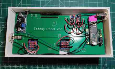
The biggest learning curve I experienced was with the PCB design. The circuit was relatively simple, with a Teensy 3.6 soldered directly to the Teensy Audio Board, The rest of the circuit was just connecting potentiometers, switches, power, and the LCD display. Learning to design a PCB with this relatively simple circuit meant there were fewer mistakes to be made. Any mistake that did make it onto the board could be fixed with a soldering iron.
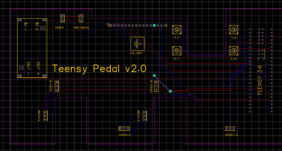
I had to make the PCB just the right size to fit in the case without too much slop and also have cutouts for the components that would stick through the PCB once inside the case. One thing I learned from this project is to never trust a template someone else made. I ordered a batch of my design only to find out that the thru-holes were too small for the pins on the Teensy to fit through. Whoever made that template: you wasted $30 of mine. I hope you're happy.
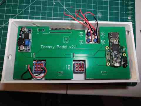
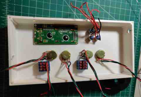
After the week spent designing the PCB and another week for shipping, I finally had my PCBs. Holy crap, having a PCB was so much better than spaghetti wires. There was no guesswork involved with if a wire was going to the right place or not; I just spent a week doing that. All of my projects will have PCBs now.
I want to provide a high-level overview of what the software on the µController is doing. If you want straight code, check out my github. I made use of the Teensy Audio Library. This amazing piece of software includes a web based GUI to setup the path for a signal and simple functions that configure and manage the c++ objects that do the actual audio processing.
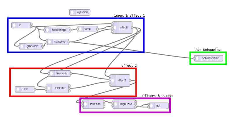
The unconnected block at the top (sgtl5000) creates an object that doesn't process any audio, but acts as the controller for the audio board. Things like output level, headphone jack enable/disable, and input level are set through this object.
Waveshape blocks allow us to change the general shape of the waveform it receives. We can very simply recreate the same hard-clipping the my distortion pedal makes. Currently, it is used to amplify the signal to the point of being a square wave. The loud output is brought down to reasonable levels by the amp right behind it. (amplifying by negative amounts results in attenuation)
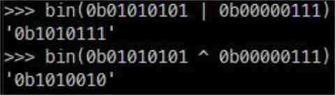
The granular block is set up to take a sample of audio, about 15ms, and play it back at faster or slower. This signal is combined with the original using bitwise operators. Unfortunately AND, OR, and XOR all sound similar. They main thing that affects the sound is the granulizer settings. With the granulized sample at full volume, all bits of the signal can be affected by the combine block. This leads to very heavy distortion. To smooth it out a bit, I added an amp block between the granulizer and combine blocks to attenuate the signal. With the OR operation, the leading 0's on the small granular signal will not affect the MSBs of the original signal. This preserves the overall characteristics of the signal while introducing some more nuanced distortion.
Despite the attenuator, the combine block does not seem to respond to the granulized signal having a lower level beyond a certain point. Changing the gain from 1.0 -> 0.5 has a small effect, but going from 0.5 -> 0.01 does not change the sound at all.
To finish up Effect 1, the mixer takes the input from whatever effect path is selected and passes it to the next stage. I also configured a wet/dry mix to allow further customization of the sound.
For Effect 2, there is a reverb effect (freeverb) and an band pass filter controlled by an LFO. The filter swings between 2 frequencies based on the "voltage" it receives from the LFO. The LFO is simply a sine wave generator running anywhere from 0Hz to 5Hz
I don't know how to stream audio to a website yet, so no demo track. If you really want to find out how it sounds, throw your own together. Parts are about $50 and the PCB and case files are on the github. Some soldering is required if you want to make it look professional and compact, but breadboards and jumper wires will make a working version too. Just make sure to keep the connections between the audio adapter and Teensy short.