Teensy Based Effect Pedal
22 July 2020
PCB
Soldering
Testing
Final Assembly
Programming
Final Thoughts
The previous Teensy-based pedal I made was a little bulky and the controls were clunky. This pedal will only apply 1 effect at a time, but can still contain multiple effects that can be cycled through. LEDs will display the status of the pedal. Controls are the standard stomp-switch along with 2 knobs that can be pushed like a button for additional inputs. Lastly, the enclosure is a professionally made aluminum housing from Hammond.
With limited space, the adjustable buck-converter from my previous projects wasn't going to fit. Since the input will always be 9V and the Teensy's voltage requirement is known and constant, the most cost effective solution would be a 5V regulator that can handle the current the Teensy will draw. However, I have wanted to try a power supply circuit with Zener diodes for a while, so I went with that. Zener diodes are typically installed "backwards" from a normal diode or LED. At a certain voltage, they break down and start conducting electricity in reverse, just like normal diodes. With Zeners though, the voltage across the diode is pretty much constant, even with a fluctuating input. This voltage is called the "Zener voltage".
There's a little math that needs to be done to get the circuit working. The basic idea is that with a Zener diode with a Zener voltage of 5V and an input of 9V, find how much voltage the resistor needs to drop. Combine this with the current requirements of whatever you're trying to power and that gives you the value for the resistor.
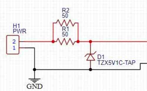
In the above diagram, there are 2 resistors in parallel. The result of my calculations showed that I needed 25Ω. Given the power that the resistor would have to dissipate, I could not find a good selection. However, I could find 50Ω resistors that can handle half the wattage needed. Put 'em in parallel and I've got a 25Ω equivalent that can handle the power required, at the cost of a little extra space.
For the PCB design, I used EasyEDA since that is the software I am most familiar with.
I checked EasyEDA's library for the footprints of the specific components I am using, but only found a few. For the others, Mouser.com provides the footprints that I could import into EasyEDA. There was some issue that prevented me from linking the circuit-diagram model to the PCB-layout model, but the circuit was simple enough that I could complete those portions within the PCB editor.
In order to fit everything inside the enclosure, I spent some time laying everything out in the enclosure to get a feeling for where everything will fit. Measurements were taken and this was translated to a PCB. Components are then placed and all the connections drawn (called ratlines).
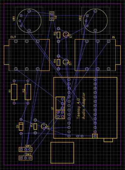
The first step to making these connections real is the ground plane. This covers the entire board with copper that will connect to ground. This helps reduce interference. But the main reason is that people who are better at this than me do it, so I'm going to as well. The auto-route function in EasyEDA will cut a path through this plane for the traces.
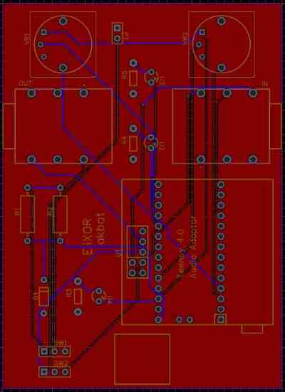
This has a chance to fail for a few connections or draw a weird path that doesn't make much sense. After checking everything though, there were no mistakes.
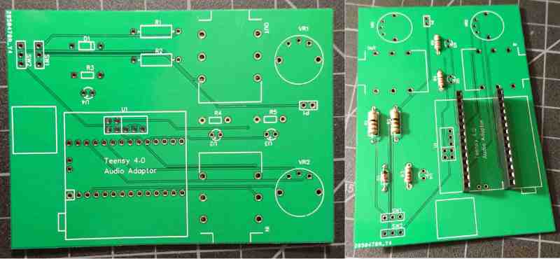
After a quick double check that all the through-holes are large enough for the pins of the components, the project was exported as gerber files and ordered. The gerber files can be found on my github.
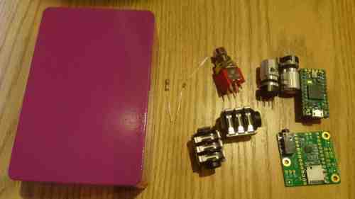
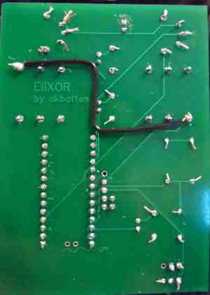
Once I got the PCBs, I got to soldering everything to them. I started with the low-profile components like resistors. I also chose to add female-headers to the board instead of soldering the Teensy directly to it. This would make it easier to remove it if something breaks or I just want to gut the project for spare parts.
Next came the taller components. The LEDs are what define the distance between the case and PCB, however the input/output jacks are what actually set the distance in the final fit.
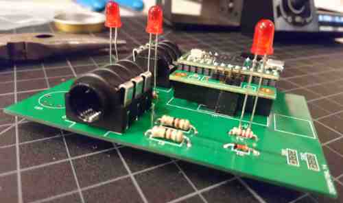
Lastly were the control knobs and stomp-switch. These needed extension wires so they could be attached to the top of the case and still make room for the other components.
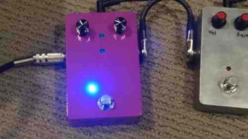
The first test was a slightly more complex version of the "blink" program that serves as "hello world" in the world of Arduino. This serves to double check the functionality of the LEDs and input controls. This does not test the audio jacks, stomp-switch, or power supply circuit. The LED closest to the foot-switch (right) is tied directly to the Teensy's power supply, so it will be on whenever the Teensy is on. The middle one blinks at a frequency based on one of the knob's position. The left-most LED turns on if a button is pushed.
The next test was the pass-through check. The pedal was inserted into the effect chain for my bass guitar and left off. This resulted in a loud buzzing sound and no response from plucking a string. After checking the circuit, I discovered the cause was the input and output grounds not being connected. The pass-through state for this pedal is "true bypass", meaning when the pedal is off, the signal goes completely around any circuits that could affect it. This requires that the input and output share a ground connection. I fixed this by adding a piece of wire on the bottom of the PCB.
Ignore the sloppy cutting of the component legs. I don't have angled wire cutters, so I can only cut them so short.
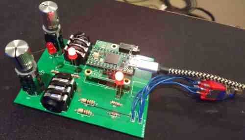
After a simple voltage check for the power supply, the entire system was ready for testing. A program was uploaded that applies a simple fuzz effect. This worked successfully, showing that all components functioned properly.
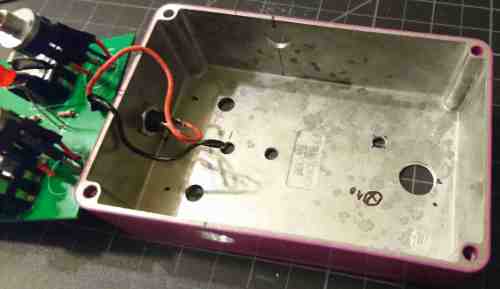
Holes were marked on the inside of the case for the controls and LEDs. These weren't measured super carefully as all components have a little wiggle room from the PCB. Except for the input/output jacks. These were marked as precisely as I could since they can't move and also hold the PCB in place. The power jack connection to the board is made in a way that isn't easily removed. I used a little extra wire so I can still take the board out of the case if I need to work on it. A better solution would be to add a connector on the board that could be removed.
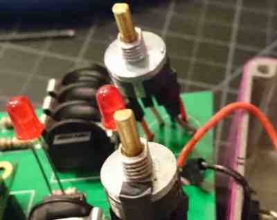
The knobs came with a small notch that is meant to interface with a small indent in whatever part they are mounted to. This keeps the body of it from rotating with the actual rotor. In my case, the pressure from the nut is enough to keep them in place. Rather than making a hole for the notch, I filed them off so that the knobs fit flush with the case. Otherwise, they would stick out at an angle. The picture below shows the top potentiometer with the notch still on the right side. The bottom potentiometer's notch has been removed.
With everything in place, the pedal was tested fully. A few problems arose after playing through a few songs. The Teensy worked its way out of the headers on the board, disconnecting itself. The solder on the bottom didn't allow the pins to be fully seated in the female headers on the board. A small file took off some solder, allowing the Teensy to be seated more firmly. I also replaced the red LEDs with blue ones. These are brighter and fit with the purple case better in my opinion.
Like my prototype pedal, the Teensy audio library was used to implement all effects. This library creates objects that each act on the signal in some way and then pass it on through connection objects to the next processing object.
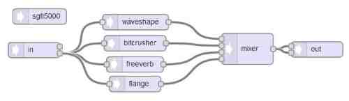
All blocks are declared at the start and the "mixer" is used to select which chain with be passed to the output. This flow-graph is almost a simple as it gets. The library also includes many other synthesizer, filter, recording/playback, and effect blocks.
This pedal can only apply 1 effect at a time. This decision was made based on the number of controls that are available. However, I programmed in 3 effects that can be cycled through by pushing the volume knob. These are fuzz, bit-crusher, and reverb. I plan to put in a flange effect in the future. Flange requires at least 2 controls to be effective. This can be done by holding the effect knob down to set the second parameter.
To achieve the fuzz effect, the waveshape block is given a somewhat odd array to map to. To create this array, we start with two reference arrays.
float refPassthrough[] = {-1.0, -0.875, -0.75, -0.625, -0.5, -0.375,
                    -0.25, -0.125, 0.0, 0.125, 0.25, 0.375, 0.5, 0.625, 0.75, 0.875, 1.0};

float refMaxFuzz[] = {-1.0, -0.966, -0.933, -0.9, -0.87, -0.82,
                -0.75, -0.15, 0.0, 0.15, 0.3, 0.35, 0.5, 0.57, 0.6, 0.65, 0.7};
The first array is linear scale with 17 steps. With this array, the waveshaper does not change the signal at all. Any deviation from this results in a different signal. This array can also be used as a reference for what an incoming, clean signal will look like. At maximum fuzz, a signal value from the refPassthrough array will be mapped to the corresponding value in the refMaxFuzz array. This method can help visualize what a fully fuzzed signal will look like.
The actual array that is given to the waveshape block is somewhere in between these two arrays. The value from the potentiometer/knob tells the controller if the actual values should be closer to refPassthrough or refMaxFuzz.
The other effects are trivial to implement with the Teensy audio library.
The full program can be found on my github.
This project turned out fantastic. All effects work perfectly and the final product looks right at home next to my other pedals. The metal enclosure and aluminum knobs make the stompbox much sturdier than my prototype which had a 3D printed enclosure and plastic knobs. This will be a pedal that stays on my board for a long time.