Tape-measure Yagi antenna
25 August 2020
While looking into satellite communications (weather and amateur radio satellites), I decided I needed a directional antenna. Some sources say that an omnidirectional antenna, like a dipole or rubber-ducky, can work. However, I wanted to eliminate any sources of problems that I could. Also, building antennas is fun.
I found plans for a simple, 3-element, yagi-uda antenna. It uses a tape-measure for the elements, 1/2" PVC for the structure, and hose clamps to hold them together. A short piece of wire and some coax cable are also needed. A 25 foot tape-measure, PVC pipe/connectors, and hose clamps cost me $30. The project took less than an hour to complete. It could be done in less than 30 minutes if you don't measure once, cut twice like I did.
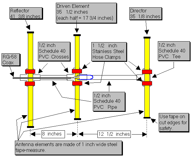
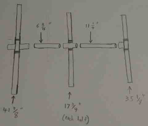
The plans I found included a technical drawing showing how long each element should be and how far away they should be from each other. The plans are in imperial. I decided to stick with inches since the tape-measure only has imperial markings.
The one issue that requires some attention and math is figuring out how long to cut the PVC. I needed to figure out how much the connector added to the length. This information might be online, but I made my own measurements.
For the reflector-driven PVC pipe, the total length is 8 inches. The problem is that when the pipe is inserted into the connector, it doesn't go all the way to the middle. We need to find out how far away it is from the center and cut the pipe that much shorter (on each end). Length 1 is the center of the connector to the end. Length 2 is how far the pipe goes into the connector.
8 - ((length 1 - length 2) * 2) = pipe length
I did this again with the driven-director pipe, replacing 8 with 12.5 Below is a diagram with measurements for construction rather than antenna analysis.
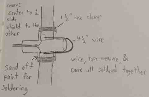
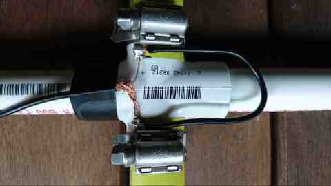
The next step was to solder the coax to the 2 halves of the driven element. Note that the driven element is just a dipole, which means the coax shielding goes to one side and the center wire goes to the other. The addition of a reflector and director element affect the impedance of the dipole, so a short (4.5") piece of wire in the shape of a U is added. This connects the two halves while adding some inductance to the circuit. If you don't know what these terms mean, don't worry about it. Just add the wire and it'll work.
I centered each element on it's PVC connector and used the hose clamps to secure them. Then everything is shoved onto the pipe. I didn't use glue or anything else to hold the PVC together. This way, I can quickly take the antenna apart for transport. It also saves a little bit of time and money.
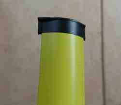
The ends of the tape-measure were very sharp. I put some electrical tape on the ends to keep them from cutting anybody.
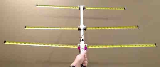
The final product is light enough to hold with one hand for ~20 minutes. It is also easy to fold up since the tape measure is made to bend and snap back into place. If I make another one, I will look into ways to make it even lighter.
To test the directivity of the antenna, I set up a receive station using an RTL-SDR and a dipole. I then transmitted with the yagi pointed in different directions. I did not take precise measurements, but the strength was greatly reduced when the yagi was pointed away from the dipole.