Building a Distortion Pedal
14 April 2019
I play bass guitar and I mess around with electronics, so building my own pedals made perfect sense. A simple distortion pedal may be the simplest, making it ideal for amateurs (me). There are differences between "distortion," "overdrive," and "fuzz." I think this pedal is technically an overdrive pedal, but I think most people understand this category of effects as "distortion," so thats what I'm going with.
If you want to learn a little theory about why this circuit works, go to this page: Theory. If you just want to build the pedal or already know the theory, read on.
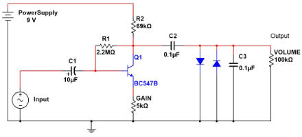
First, the schematic:
This build requires the following tools:
Soldering Iron w/solder
Screwdriver
Some way to cut through your case (I used a drill and file)
I also needed some components:
Transistor
Various resistors
2x potentiometers (volume/gain knobs)
Wire
Button/switch (or anything to turn the pedal on/off)
1/4" jacks for plugging cables into
Something to put all this in
9v DC power supply
DC jack
LED
The 1/4" jacks can be ordered online, but you may also find some in a music shop. You only need the ones with 2 contacts: one for ground and one for the signal.
I would recommend building this circuit in a breadboard before soldering it. This will give you a chance to listen to it and see if you like it or if you need to adjust some components. For example: reducing the value for C1 makes the circuit more responsive with guitars, but reduces the effect for basses. I play bass, so I used 10µF. You can also remove C3 entirely to get a harsher sound. I actually ended up doing this. You can also use different transistors to get slightly different sounds.
One note: the gain potentiometer connected to act as a variable resistor. The volume potentiometer is connected to act as a voltage divider. The incoming signal is connected to the middle pin, ground to one side, and the output to another. If the volume knob works backwards, switch the ground and output lines.
After breadboarding the circuit and settling on a final design, I started to make the circuit permanent by soldering it into perfboard. Once this was complete, I tested the circuit again to make sure it still worked. I then put some tape on the back to isolate all the wires from the aluminum box this was going in.
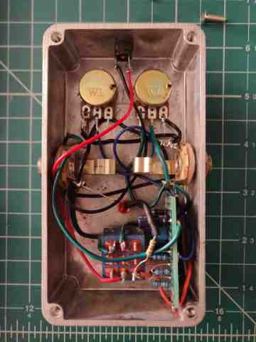
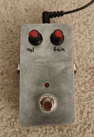
For the case, I drilled two holes on either side for the jacks. I should have thought about the layout more carefully; everything ended up being really cramped. The jacks were pushed into the hole from the inside and have a nut on the outside to keep them in place. I then drilled 2 holes for the volume and gain knobs and another for the switch. I found a switch online designed for use in guitar pedals. This goes in the same way as the jacks. The knobs (potentiometers) are simply friction fit into their holes (shoved in so tight they aren't going to come out).
Later on, I put a hole in the back of the pedal for power and another right above the switch for the LED. This LED indicates if the pedal is on or not. A 220Ω resistor limits the current and keeps the LED from exploding.
The switch is wired so that in one state, it disconnects power and also connects the input directly to the output. This bypasses the effect and lets me play without it. In the other state, it connects power and disconnects the bypass.
The after wiring up all the knobs and switch, the bottom of the case was screwed on and the pedal is ready to go.